Introduction to data formats utilized by TASTE
In this text, file formats actually utilized by TASTE will be presented in brief. First, Templatized module type library format and then, Netlist format will be presented. Of course, it is possible to design own formats or utilize existing ones to work with TASTE. In such a situation, it is necessary to write corresponding functions for loading and/or saving such file formats.Templatized module type library format
Actual syntax of a language utilized by TASTE to store transparency properties related to particular module types can be expressed by means of following Backus Naur Form (BNF ):
    <lib_element> ::= MODULE_TYPE <mt> INTERFACE <it><info> IMPL <impl> <lib_element>
    <mt> ::= <identifier> | <identifier>"<"<parameters>">" | "<"<parameters>">"<identifier>
    <parameters> ::= <identifier>|<identifier>_<parameters>
    <it>::= <identifier>@<it_range>|<identifier>@<it_range> <it>
    <it_range> ::= [<number>]|(<number>:<number>)
    <info> ::= TRANS <sur> TRANI <inj> TRANIS <bij>
    <impl> ::= area@<expression> power@<expression>
    <sur> ::= <identifier><map_range>|<identif.><map_range><sur>
    <inj> ::= <identifier><map_range>|<identif..><map_range> <inj>
    <bij> ::= <identifier><map_range>|<ident.r><map_range> <bij>
    <map_range> ::= [<expression>]|(<expression>:<expression>)
As an example of such formatted file, you can see taste.templates file distributed along with TASTE.
C++ end-to-line comments starting with "//" can be utilized in the file. Let some ilustrative examples be presented now rather than detail study of the BNF. In Read about transparency conception before using TASTE, ilustration related to two-input multiplexer module type
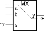
ilustration module type description format
    MODULE_TYPE MX_2
    INTERFACE in@a[n] in@b[n] in@s[1] out@y[n]
    IMPL area@2*n+1 power@n/0.03
    TRANI                                        // not used in actual TASTE version
    TRANS                                        // not used in actual TASTE version
    TRANIS a(i)|y(i)|s(0) b(i)|y(i)|s(0)
    TRND                                         // not used in actual TASTE version
In Netlist format section, it will be shown how particular modules can be declared by means of above-mentioned information. For example, if an 2-input multiplexers (of type MX_2) named MUX2a and MUX2b are to be involved in the design, it is necessary to add following lines into a netlist file (netlist cutout):
    ITM MUX2a(MX_2)
    ITM MUX2b(MX_2)
Above-mentioned example of module-type definition described transparency information for one particular module-type only (2-input multiplexer). It was the simplest way of utilizing the language. But, the language is more powerful! By means of the language, it is possible to describe a more general information covering entire class of circuits, e.g., n -bit registers or adders.
    // one template for R_4, R_32, etc. declaration in netlist
    MODULE_TYPE R_<n>
    INTERFACE in@d(n-1:0) in@clk(0) out@y(n-1:0)
    ...
    TRANIS d(n-1:0)|y(n-1:0)|clk(0)
    ...

    // one template for ADD_4a, ADD_16a, etc. declaration in netlist
    MODULE_TYPE ADD_<n>a
    INTERFACE in@a[n] in@b[n] out@y(0:n-1)
    ...
    TRANIS a(n-1:0)|y(n-1:0)|b(n-1:0) b(n-1:0)|y(n-1:0)|a(n-1:0)
    ...
As an example, let following netlist cutout be presented in order to illustrate utilization of above-defined module-types.
    ITM r1(R_4)
    ITM r2(R_32)
    ITM adder1(ADD_8a)
    ITM adder1(ADD_16a)
Netlist format
Actual syntax of a language utilized by TASTE to store a netlist containing information about circuit structure can be expressed by means of following Backus Naur Form (BNF ). In actual TASTE version, only one clsCircuit object is supported within a clsDesign object. The disadvantage shoud be removed in next TASTE version.
    <cir> ::= CIR <identifier> <it> <itm> <link>
    <it> ::= <identifier>(<port_type>)|<identif.>(<port_type>) <it>
    <port_type> ::= in|out|inout|clk|sel
    <itm> ::= ITM <identifier> (<com_type>)|    <identifier>(<com_type>) <itm>
    <link> ::= LINK <identifier> -> {<identifier>}|
    <identifier> -> {<identifier>} <link>
As an example of such formatted file, you can see nl file distributed along with TASTE and containig netlist of below-presented myCir circuit.
C++ end-to-line comments starting with "//" can be utilized in the file. Let some ilustrative examples be presented now rather than detail study of the BNF.
Suppose structural information about circuit named myCir is to be stored in the netlist and suppose myCir should have interface consisting of input 4-bit port named in, 1-bit clock port named clk and out 4-bit port named out.
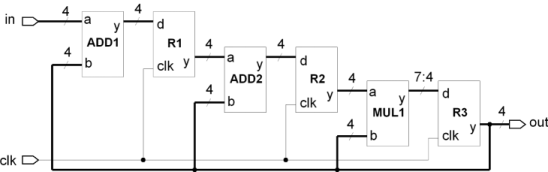
structure of myCir circuit
    CIR myCir in(in,4) clk(clk,1) out(out,4)
    // 'in' before '(' is name of the port
    // 'in' inside '(...)' is type of the port
    // number 4 inside '(...)' is bit-width of the port
Now suppose at least following module-types are defined according to information present in Templatized module type library format section:
    MODULE_TYPE ADD_<n>a
    INTERFACE in@a[n] in@b[n] out@y(0:n-1)
    IMPL area@0 power@0
    TRANI
    TRANS
    TRANIS a(n-1:0)|y(n-1:0)|b(n-1:0) b(n-1:0)|y(n-1:0)|a(n-1:0)
    TRND

    MODULE_TYPE MUL_<n1_n2>comb
    INTERFACE in@a[n1] in@b[n1] out@y(n2-1:0)
    IMPL area@0 power@0
    TRANI
    TRANS
    TRANIS a(n1-1:0)|y(7:4)|b(n1-1:0) b(n1-1:0)|y(7:4)|a(n1-1:0)
    TRND

    MODULE_TYPE REG_<n>
    INTERFACE in@d(n-1:0) clk@clk[1] out@y[n]
    IMPL area@0 power@0
    TRANI
    TRANS
    TRANIS d(i)|y(i)|clk(0)
    TRND

    MODULE_TYPE MUX_<n1>
    INTERFACE in@a[n1] in@b[n1] in@sel(0) out@y(n1-1:0)
    IMPL area@0 power@0
    TRANI
    TRANS
    TRANIS a(n1-1:0)|y(n1-1:0)|sel(0) b(n1-1:0)|y(n1-1:0)|sel(0)
    TRND

    MODULE_TYPE SREG_<n>
    INTERFACE in@d[n] out@y[n] clk@clk[1] in@mode[1] in@s_in[1] out@s_out[1]
    IMPL area@0 power@0
    TRANI
    TRANS
    TRANIS d(i)|y(i)|clk(0)mode(0) s_in(0)|y(i)|clk(0^i)mode(0) d(i)|s_out(0)|clk(0^i)mode(0) s_in(0)|s_out(0)|clk(0^n)mode(0)
    TRND
Now, above mentioned CIR section of the netlist can be extended about ITM section. This will ensure all modules (of particular types) needed for construction of circuit structure will be declared.
    CIR myCir in(in,4) clk(clk,1) out(out,4)

    // ITM section added:
    ITM ADD1(ADD_4a)
    ITM ADD2(ADD_4a)
    ITM MUL1(MUL_4_8comb)
    ITM R1(REG_4)
    ITM R2(REG_4)
    ITM R3(REG_4)
After circuit interface and modules are declared, it is possible to interconnect module interfaces among themselves and with circuit interface. Thus, above mentioned CIR and ITM sections of the netlist can be extended about LINK section. Final netlist is as follows:
    CIR myCir in(in,4) clk(clk,1) out(out,4)

    ITM ADD1(ADD_4a)
    ITM ADD2(ADD_4a)
    ITM MUL1(MUL_4_8comb)
    ITM R1(REG_4)
    ITM R2(REG_4)
    ITM R3(REG_4)

    // LINK section added:
    LINK myCir.in(0:3) -> ADD1.a(0:3)        // you can explicitly change wiring
    LINK myCir.clk -> R1.clk                 // implicit wiring (i <-> i)
    LINK myCir.clk -> R2.clk
    LINK myCir.clk -> R3.clk
    LINK ADD1.y -> R1.d
    LINK R1.y -> ADD2.a
    LINK ADD2.y -> R2.d
    LINK R2.y -> MUL1.a
    LINK MUL1.y(7:4) -> R3.d                // other version of explicit wiring
    LINK R3.y -> ADD1.b ADD2.b MUL1.b myCir.out
By means of above-mentioned module-type MUX_<n1> and SREG_<n> templates, try yourselves to solve following odifications to myCir structure:
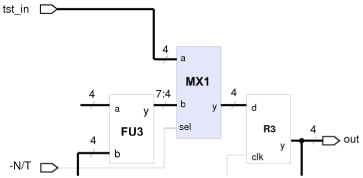
multiplexer MX1 added between MUL1.y and R3.d
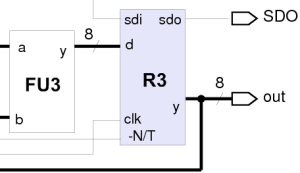
register R3 modified to scan